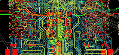
Automated PCB Stackup Design and Verification

Manage the PCB stackup design process from concept to fabrication
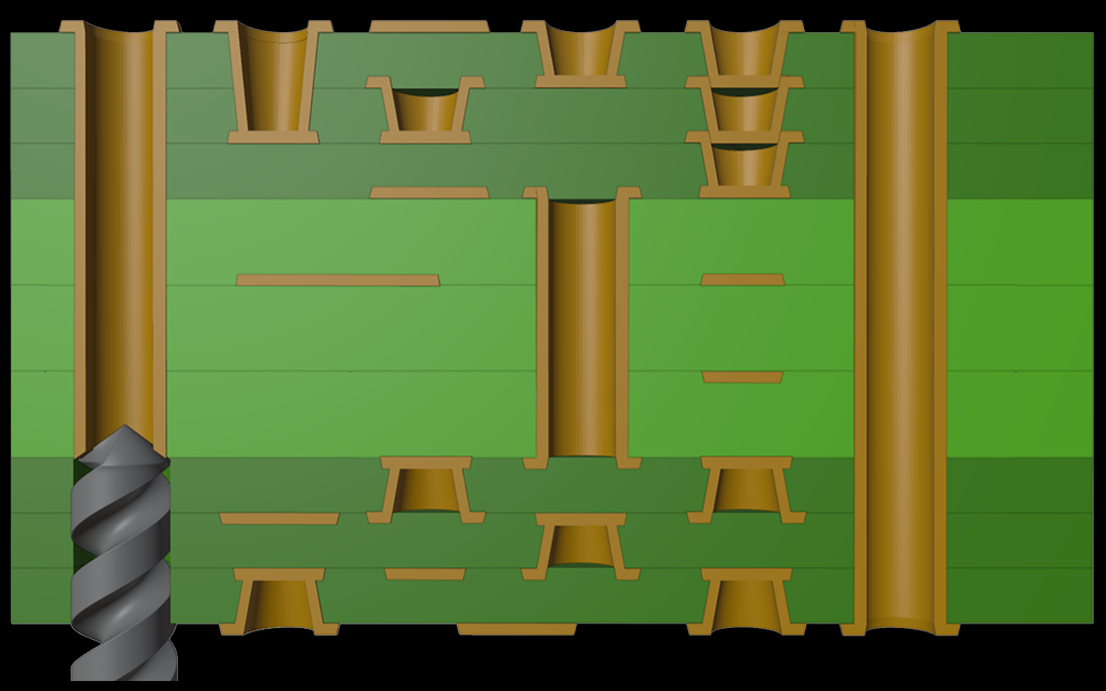
Stackup Design

Z-zero PCB stackup design software enables you to design for Zo, Zdiff, insertion loss, and via planning with automation that help you create stackups that are optimized for both signal integrity and power integrity
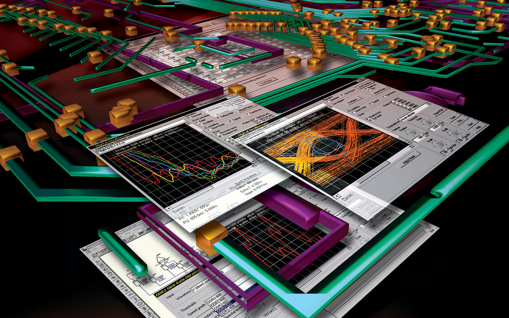
PCB Stackup Verification

Z-planner Enterprise provides a direct, automated means of comparing fabricator stackups against specifications, including comprehensive DFM and DFSI checking.
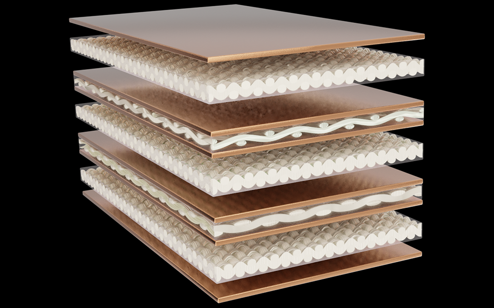
PCB Material Selection

The most comprehensive PCB materials library in the industry, including frequency-dependent Dk and Df for major high-speed PCB laminates out of the box. Detailed copper roughness data. Match materials for potential cost reductions. Filter on every material parameter you can think of.
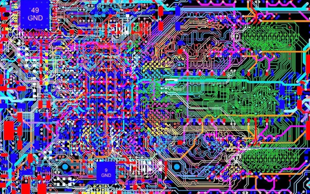
PCB Software Interfaces

Z-planner Enterprise includes import/export utilities for 18 PCB stackup formats, eliminating the tedious, error-prone process of entering stackups from PDFs. Supported formats include Excel, IPC-2581, HyperLynx, InStack, Polar, Xpedition, and Altium Designer. 

PCB Software

Z-zero PCB stackup design software enables you to solve for Zo, Zdiff, insertion loss, and propagation delay with an industry-leading, user friendly interface and a comprehensive PCB materials library.

PCB Interfaces​

Z-planner Enterprise includes import/export utilities for 16 PCB stackup formats, eliminating the tedious, error-prone process of entering stackups from PDFs. Supported formats include Excel, IPC-2581, HyperLynx, InStack, Polar, Xpedition, and Altium Designer.

PCB Materials

The most comprehensive PCB materials library in the industry, including frequency-dependent Dk and Df for major high-speed PCB laminates out of the box. Detailed copper roughness data. Match materials for potential cost reductions. Filter on every material parameter you can think of.

About Z-zero

As signaling speeds increase, manufacturing details are critical in signal integrity simulation and Z-zero software eliminates communication issues between hardware design teams and the PCB supply chain.


Z-zero enhances the stackup design process with a field-solver enabled loss-planning environment, and a complete dielectric materials library — all seamlessly interfaced to the most popular signal-integrity software.
Contact Us

Whether you have a question about features, trials, pricing, need a demo, or anything else.

    Frequently Asked Questions

    Yes. At high frequencies, current increasingly flows through the perimeter of a signal conductor. This is referred to as the “skin effect.” The depth at which the current flows is called “skin depth,” and is typically denoted by d (um). As frequency increases, skin depth gets progressively smaller. As skin depth approaches the surface roughness of the copper, they must be considered together when simulating signal attenuation. There are several ways to measure copper roughness, but the most commonly-available parameter is Rz (um), so Z-planner utilizes this parameter rather than other alternative roughness measures to simulate copper roughness loss as a function of frequency.
    Hard disk space: 100MB —Minimum 4GB RAM —64 bit Windows 7.x, 8.x, or 10.x
    Yes, using Flexera FlexNet Licensing
    • Currently, Z-planner imports and exports the HyperLynx format (.STK, .FFS), as well as IPC-2581 and ODB++ formats.
    • We’re working on interfaces to Keysight ADS, Sigrity Speed2000, Simberian Simbeor and SiSoft.
    Z-planner uses Mentor Graphics’ time-tested HyperLynx® 2D field solver.
    Yes, under Settings.
    Yes, dielectric constant (Dk), dissipation factor (Df), are interpolated from material tables that vary with frequency. Loss, too, is frequency dependent.
    Yes. At high frequencies, current increasingly flows through the perimeter of a signal conductor. This is referred to as the “skin effect.” The depth at which the current flows is called “skin depth,” and is typically denoted by d (um). As frequency increases, skin depth gets progressively smaller. As skin depth approaches the surface roughness of the copper, they must be considered together when simulating signal attenuation. There are several ways to measure copper roughness, but the most commonly-available parameter is Rz (um), so Z-planner utilizes this parameter rather than other alternative roughness measures to simulate copper roughness loss as a function of frequency.
    Hard disk space: 100MB —Minimum 4GB RAM —64 bit Windows 7.x, 8.x, or 10.x

    Testimonials

    What Our Customers Say

    Download a free software evaluation 
and take it for a spin on your own.

    Eliminate manual data reentry and interface with the most popular signal-integrity software

    Download a free software evaluation 
and take it for a spin on your own.

    Eliminate manual data reentry and interface with the most popular signal-integrity software